

Terrain / Terrain DEM
Reveal the ground.
Turn a full point cloud into a ground-oriented elevation surface. Inspect fitted ground and reconstructed estimates, then carry the surface into CAD or GIS.
Start with
A selected analysis point cloud, spacing, ground-fitting settings and coordinate reference where known.
Create
A terrain mesh, terrain nodes, elevation rasters and quality evidence supported by the configured workflow.
Why it matters
Extract a practical terrain representation while keeping its relationship to the original observations visible.
How terrain dem works.
- 01
Choose the analysis cloud
Select the source PLY explicitly. Apply its saved alignment when required; changing a visible layer alone does not change the analysis source.
- 02
Set terrain parameters
Choose grid spacing and the neighbouring-ground height cutoff. Supply the projected EPSG where the coordinate reference is known.
- 03
Build and review
Generate the full-cloud DEM. Compare fitted ground, reconstructed estimates and areas with no supported surface against the original scan.
- 04
Export consistently
Use the final elevation surface for node, mesh and raster outputs, keeping coordinate and quality information with the deliverable.
Read the result in context
A DEM has one elevation per XY position. It cannot represent every overhang, vertical face or stacked surface. Grid spacing is not measurement accuracy.
Take the next step.
Measurement
Volumetrics
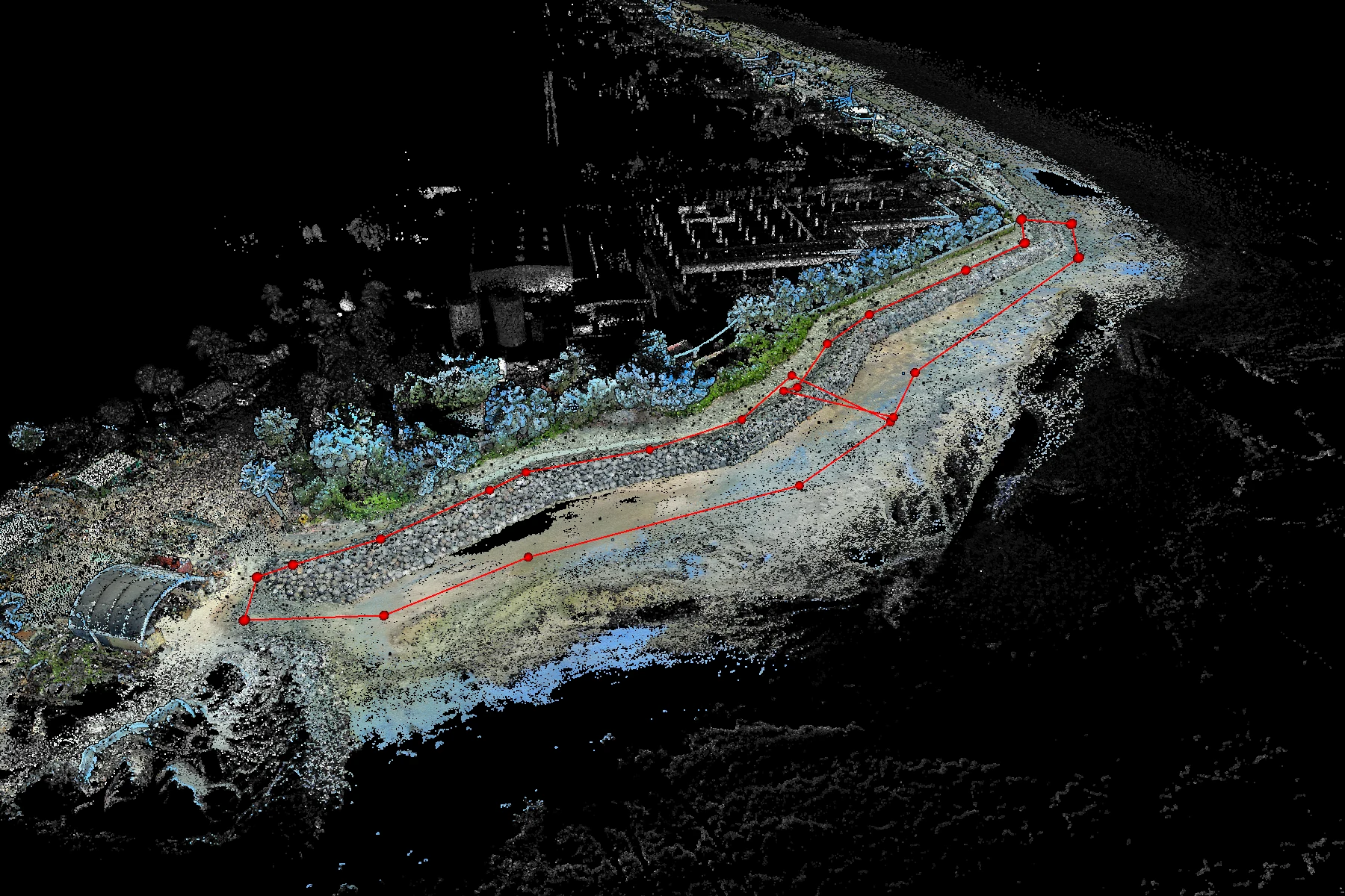
Draw an area, choose a reference base and calculate the volume between that base and the captured surface.
Explore Volumetrics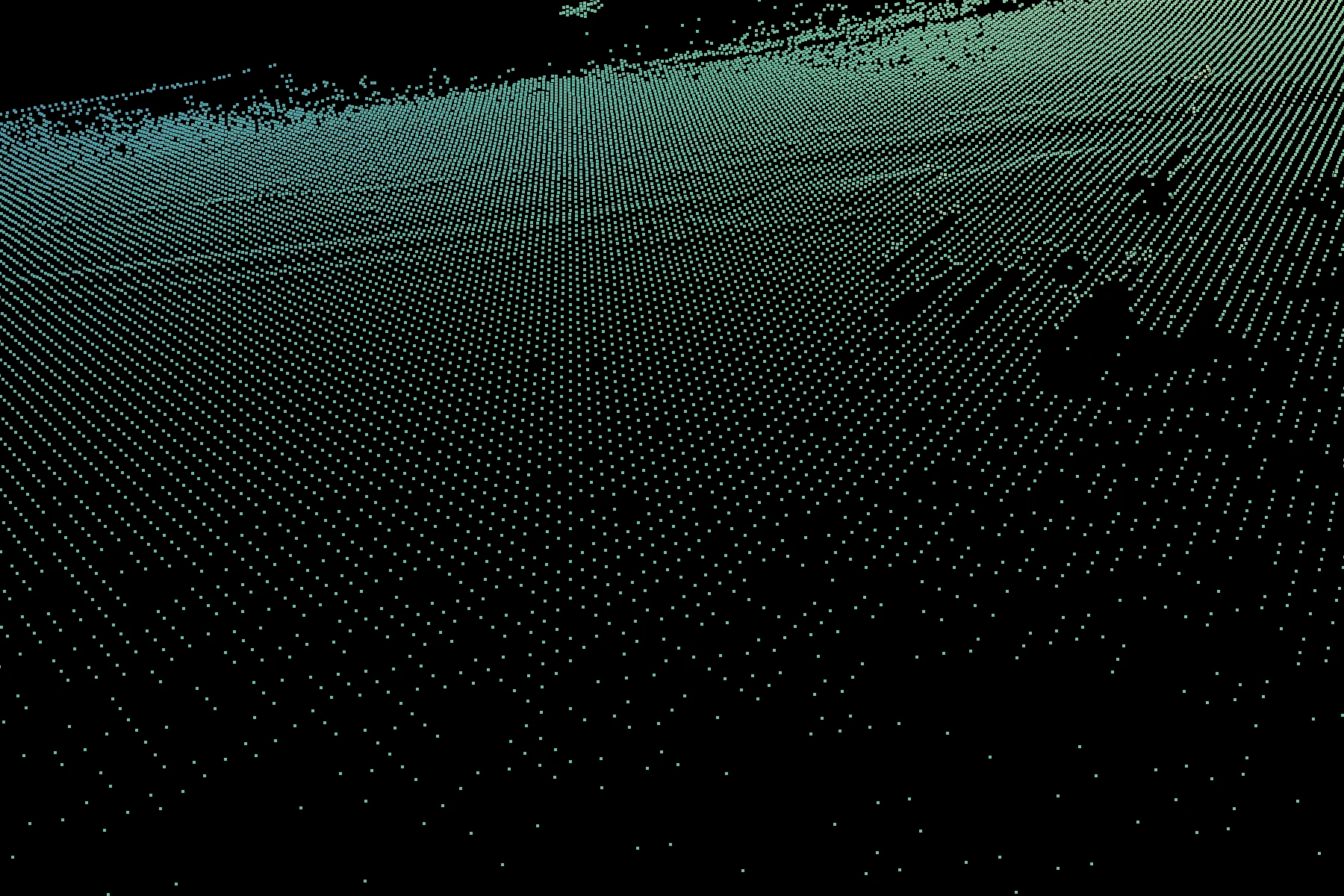
Terrain
Terrain gridding
Convert irregular survey returns into fitted terrain points at regular XY positions. Work across the recording or focus on a polygon.
Explore Terrain gridding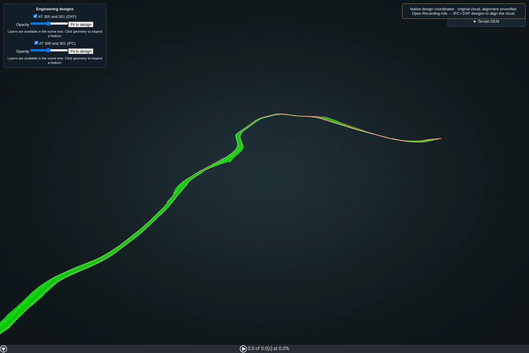
Design review
IFC & DXF design loading
Review engineering designs in the same 3D workspace as your survey. Control layer visibility and opacity to inspect geometry in context.
Explore IFC & DXF design loading